

G1 Bottle Pick-and-Lift
G1 Bottle Pick-and-Lift: Object-Relative Corrections and Real-Robot Integration
Week 3: improving integrated success with object-relative control and moving the learned policy toward real G1 deployment.
Introduction
In the previous article, I covered the following parts of the bottle grasping and lifting reinforcement learning project for the Unitree G1 Inspire Hand.
- Mass Curriculum from 0.08 kg to 0.62 kg
- Stage 2 grasp / lift policy adapted to 0.62 kg conditions
- Stage 1 Safe Approach Policy to approach without moving the dynamic bottle
- controlled ingress connecting Stage 1 and Stage 2
- Phase timing issue due to Isaac Lab's decimation
- Confirmation of checkpoint architecture and observation contract
- Termination-based formal deterministic evaluation
The main simulation results up until now were as follows.
| Module | Condition | Result |
|---|---|---|
| Stage 1 | Dynamic 0.62 kg, x/y ±1.5 cm | 768 / 768 |
| Stage 2 | Fixed nominal, 0.62 kg | 766 / 768 |
| Zero-residual bridge | Fixed nominal | Reaching Stage 2 handover |
On the other hand, at the time of the previous article, the integrated evaluation of operating Stage 2 learned residual from the actual Stage 1 handover state had not been completed.
This week, after completing this integration part, I proceeded with failure analysis of randomized workspaces, object-relative trajectory correction, and expansion to wide-area workspaces.
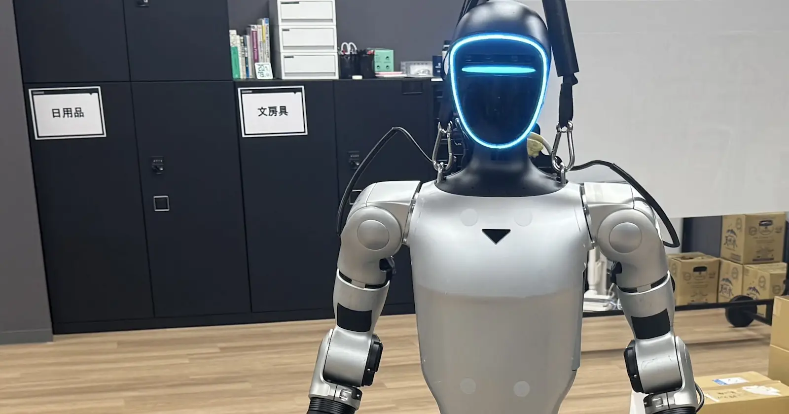
Additionally, I migrated the trained checkpoint to NVIDIA DGX Spark and built a standalone actor that does not depend on Isaac Lab. I then validated state acquisition from the real Unitree G1 and Inspire Hand, the right-arm transition to a task-ready pose, open-air hand motion, and the first bounded model-derived command.
This article summarizes the following contents.
- Nominal integration with Learned Stage 2 connected
- Coordinate semantics problem encountered with Integrated RandPos
- Object-relative ingress / lift correction
- Improvement from 55.7% to 97.4% success rate in ±1.5 cm condition
- A ±5 cm workspace and Stage 0 coarse bias
- 84.4% success in practical asymmetric workspace
- Checkpoint migration to DGX Spark
- Reconstruction of Standalone PyTorch actor
- Inference matching between Brev x86 and DGX Spark ARM64
- Initial integration with actual G1 / Inspire Hand
- Failures encountered this week and notes on implementation
- Current achievements and future challenges
The success rate in this article is a simulation result using simplified rigid-body bottle on Isaac Lab.
The real-robot work described here was conducted incrementally in a fixed standing position, under supervision, at low speed, and with either no object or a lightweight empty bottle. It does not demonstrate autonomous grasping and lifting of a filled beverage bottle, complete sim-to-real transfer, human handover, or safety certification.
Connect Learned Stage 2 to the integrated Pipeline
Last time, I confirmed that it was possible to reach Stage 2 from Stage 1 via controlled ingress.
In the first bridge diagnostic, Stage 2 residual was set to strictly zero.
learned Stage 1
  ↓
controlled ingress
  ↓
scripted Stage 2 base trajectory
  + zero residual
Although this configuration was successful in safe handover, it was not possible to lift the 0.62 kg bottle to any meaningful height.
The typical results were as follows.
| Metric | Result |
|---|---|
| Maximum center-height increase | approximately 4.8 mm |
| Final center-height increase | approximately 0.04 mm |
| Maximum horizontal displacement | approximately 43 mm |
| Strict retention / lift | False |
In other words, the geometry bridge from Stage 1 to Stage 2 was established, but a learned residual was required for grasp/retention under the 0.62 kg condition.
Therefore, I connected the selected Stage 2 checkpoint to the integrated environment.
Stage 1:
  frozen deterministic policy

controlled ingress:
  deterministic arm interpolation

Stage 2:
  scripted base trajectory
  + frozen deterministic 12D hand residual
Stage 2 actor inference runs only once per environment step, not per physics substep.
environment step:
  actor inference
  previous residual update
  target calculation

remaining physics substep:
  hold the same target
This is as important as the decimation problem I discovered last time.
If actor inference or previous residual update is executed for each physics substep, the policy will operate on a different time scale than during training.
After modification, Stage 2 actor inference count matched the expected value.
actual inference count:
  742

expected inference count:
  742
Under nominal conditions, I confirmed a meaningful lift of approximately 3.58 cm by enabling Stage 2 learned residual.
However, if the policy target continues to update after a successful lift, the bottle may gradually tilt and eventually slip.
Target Latch after successful lifting
For formal success determination, the following must be met continuously for a certain period of time.
- bottle height
- retention
- workspace
- uprightness
- safety condition
In this configuration, I used 24 consecutive valid steps as the formal success condition.
After success, I saved the last commanded hand target and added a supervisory latch to hold that target.
retention / lift success
  ↓
copy current commanded hand target
  ↓
stop updating hand target
  ↓
continue normal physics simulation
This latch fixes only the command target.
The following operations have not been performed.
- bottle attachment
- bottle freeze
- kinematic override
- teleport
- stopping physics
- Direct change of object pose
Typical results after Latch were as follows.
| Metric | Result |
|---|---|
| Commanded-target drift | 0.000000000 |
| Final retention count | 423 |
| Final center-height increase | approximately 0.0358 m |
| Final uprightness | approximately 0.969 |
As a result, I was able to confirm the following sequence of operations under the nominal condition.
Stage 1 outer approach
  ↓
controlled ingress
  ↓
Stage 2 grasp
  ↓
lift
  ↓
retention
  ↓
stable extended hold
However, this result is a hybrid control.
learned Stage 1
  + deterministic geometric bridge
  + learned Stage 2
  + supervisory target latch
Not pure end-to-end RL.
Initial result of Integrated RandPos is 55.7%
After nominal integration was established, integrated RandPos evaluation was performed by changing the bottle position by ±1.5 cm in the x/y direction.
The conditions are below.
bottle:
  dynamic simplified rigid body
  0.62 kg

randomization:
  x/y ±0.015 m

Stage 1:
  frozen model_149

ingress / lift:
  fixed nominal joint-space targets

Stage 2:
  frozen model_100

success:
  evaluated by termination_manager
  24-step retention / lift success
The results were as follows.
| Seed | Success |
|---|---|
| 42 | 145 / 256 |
| 43 | 283 / 512 |
| Combined | 428 / 768 |
The combined success rate was 55.73%.
The failure distribution was as follows.
| Outcome | Count | Rate |
|---|---|---|
| Success | 428 | 55.73% |
| Unsafe bottle disturbance | 197 | 25.65% |
| Object out of workspace | 43 | 5.60% |
| Timeout | 100 | 13.02% |
Stage 1 was 768/768 for individual evaluation, and Stage 2 was 766/768 for fixed conditions.
Nevertheless, the combined result was 428/768.
This shows that even if you multiply the success rates of individual policies, you will not get the integrated success rate.
The Problem Was Coordinate Semantics, Not Policy Performance
When I checked the failure map, I found that the failures were not random, but had a direction depending on the bottle position.
In the failure analysis of 1024 episodes, 233 out of 234 unsafe failures occurred in the area where the bottle's y offset was negative.
Also, timeout and workspace failure have increased on the positive x side.
From this result, I suspected a geometry inconsistency rather than simple PPO noise.
Stage 1 was Bottle-Relative
Stage 1 target is calculated from the bottle position.
outer_target
  = bottle_position + outer_offset
Therefore, even if the bottle moves, Stage 1 can move to the same relative position with respect to the bottle.
Ingress and lift were Nominal Joint Pose
On the other hand, ingress and lift after Stage 1 were fixed joint-space targets.
Stage 1:
  follow the displaced bottle

ingress:
  return to the nominal joint pose

lift:
  return to the nominal joint pose
In other words, it was object-relative up to Stage 1, but object-relative semantics were lost in subsequent trajectories.
bottle-relative outer pose
  ↓
fixed nominal ingress
  ↓
fixed nominal lift
This causes the hand to return to the position away from the bottle even if the bottle position changes by a few centimeters.
An important point is that before relearning checkpoints or PPOs, you need to make sure that the coordinate semantics are consistent across controllers.
Even if the learned policy is object-relative, if the subsequent scripted controller returns to nominal joint-space, the entire system is not object-relative.
Object-Relative correction using Local Jacobian
To solve this problem, I numerically measured the hand-center Jacobian around the nominal ingress pose.
The target joint is the following 4D.
- right shoulder pitch
- right shoulder roll
- right shoulder yaw
- right elbow
Hand center is the average position of the following four proximal links.
- index proximal
- middle proximal
- ring proximal
- pinky proximal
For conversion from Cartesian displacement to joint correction, I used measured Jacobian's pseudoinverse.
bottle_offset = settled_bottle_position - nominal_bottle_position

desired_hand_translation = gain × [offset_x, offset_y, 0]

joint_correction = Cartesian-to-arm pseudoinverse × desired_hand_translation
The target after correction is as follows.
corrected_ingress_target = nominal_ingress_target + joint_correction

corrected_lift_target = nominal_lift_target + joint_correction
By applying the same correction to both ingress and lift, the object-relative geometry is maintained even after starting the grasp.
Measured matrix generally had the following characteristics.
| Joint | x direction | y direction |
|---|---|---|
| Shoulder pitch | -5.28 rad/m | -1.08 rad/m |
| Shoulder roll | +0.32 rad/m | +1.21 rad/m |
| Shoulder yaw | -1.79 rad/m | +1.66 rad/m |
| Elbow | +5.40 rad/m | +1.42 rad/m |
The RMSE of the Jacobian fit was approximately 0.036 mm.
However, this is a local model around the nominal ingress pose.
This does not mean that you can directly extrapolate to ±10 cm or ±15 cm.
Comparison of Correction Gain
Correction gain was compared under x/y ±1.5 cm conditions.
| Gain | Success |
|---|---|
| 0.00 | 82 / 128 |
| 0.50 | 116 / 128 |
| 0.75 | 124 / 128 |
| 1.00 | 126 / 128 |
I selected Gain 1.0 and conducted a formal evaluation.
The following remains unchanged.
- Stage 1 checkpoint
- Stage 2 checkpoint
- PPO weight
- observation
- residual scale
- self-collision
- bottle physics
- formal success condition
- unsafe threshold
No additional training is provided.
Success rate 97.4% at ±1.5 cm
The formal evaluation results with Object-relative ingress/lift correction enabled are shown below.
Seed 42
| Outcome | Result |
|---|---|
| Success | 253 / 256 |
| Unsafe | 0 |
| Workspace | 0 |
| Timeout | 3 |
Seed 43
| Outcome | Result |
|---|---|
| Success | 495 / 512 |
| Unsafe | 0 |
| Workspace | 3 |
| Timeout | 14 |
Combined
| Outcome | Result | Rate |
|---|---|---|
| Success | 748 / 768 | 97.40% |
| Unsafe | 0 / 768 | 0% |
| Workspace | 3 / 768 | 0.39% |
| Timeout | 17 / 768 | 2.21% |
A comparison before and after correction is as follows.
| Metric | Before | After |
|---|---|---|
| Success | 428 | 748 |
| Success rate | 55.73% | 97.40% |
| Unsafe | 197 | 0 |
| Total failures | 340 | 20 |
Success increased by 320 episodes.
Failures decreased from 340 to 20, a decrease of approximately 94.1%.
The success rate improved by 41.67 percentage points without any additional PPO and just by modifying the coordinate semantics.
This was the most important result of the week.
Before scaling or retraining the policy, verify that frame and target semantics remain consistent between learned and geometric control.
Extending the Workspace to ±5 cm
Next, I extended the bottle position range to x/y ±5 cm.
First, I evaluated it using only the same object-relative correction and without adding Stage 0.
The results were as follows.
| Outcome | Count | Rate |
|---|---|---|
| Success | 536 / 768 | 69.79% |
| Unsafe | 20 / 768 | 2.60% |
| Workspace | 2 / 768 | 0.26% |
| Timeout | 210 / 768 | 27.34% |
The conditional success after reaching Stage 2 was approximately 91.94%.
Stage 2 reached:
  583 / 768

success after Stage 2:
  536 / 583
In other words, if I could reach Stage 2, I would have succeeded in grasping/lifting in many episodes.
The main bottleneck was that Stage 1 had a large workspace and could not reach the outer gate.
In particular, the positive y direction was weak, and the following results were obtained for the bin at y=+4 to +5 cm.
samples:
  51

outer gate:
  0 / 51

success:
  0 / 51
In this area, even if the episode duration was extended, the target could not be reached.
Stage 0 Coarse Bias
The Stage 1 policy was originally learned with a local capture range of ±1.5 cm.
Therefore, I added a deterministic Stage 0 before Stage 1.
The purpose of Stage 0 is to remove only the portion of the wide workspace offset that exceeds the Stage 1 local range.
bottle_offset
  ↓
local_offset
  = clamp(bottle_offset, -0.015, +0.015)

coarse_translation
  = bottle_offset - local_offset

Stage 0 bias = safe-pose Jacobian pseudoinverse × coarse_translation
The execution order is as follows.
Stage 0:
  60-step smooth coarse motion
  ↓
Stage 1:
  frozen local safe approach
  ↓
object-relative ingress / lift
  ↓
Stage 2
Stage 0 is a geometric controller that uses measured local Jacobian around safe pose instead of learned policy.
The selected settings are below.
local capture half-range:
  0.015 m

coarse steps:
  60

correction bound:
  0.24 rad
Results for Full ±5 cm Square
The formal evaluation results for full x/y ±5 cm square with Stage 0 enabled are as follows.
Seed 42
success:
  193 / 256
  75.39%
Seed 43
success:
  376 / 512
  73.44%
Combined
| Outcome | Count | Rate |
|---|---|---|
| Success | 569 / 768 | 74.09% |
| Unsafe | 16 / 768 | 2.08% |
| Workspace | 21 / 768 | 2.73% |
| Timeout | 162 / 768 | 21.09% |
Comparison with without Stage 0 is below.
| Metric | Without Stage 0 | With Stage 0 |
|---|---|---|
| Outer gate reached | 601 | 750 |
| Stage 2 reached | 583 | 737 |
| Success | 536 | 569 |
Stage 0 has improved the majority of Stage 1 reach failures.
On the other hand, the success rate after reaching Stage 2 decreased to approximately 77.2%.
So, after being "reachable" at Stage 0, the next bottleneck was handover geometry at wide-area locations and Stage 2 compatibility.
Failure Analysis in the Positive-y region
When analyzing 162 Full square timeout cases, 147 of them reached Stage 2.
The initial position averages of successful episodes and timeout episodes had the following trends.
| Outcome | Mean x | Mean y |
|---|---|---|
| Success | -0.0014 m | -0.0106 m |
| Timeout after Stage 2 | +0.0088 m | +0.0248 m |
| Workspace failure | +0.0244 m | +0.0093 m |
On the positive y side, I thought that the grasp geometry would easily deviate from the Stage 2 training distribution.
So I tried the following.
- global ingress gain
- positive-y trim
- pre-contact alignment
Global Gain 1.04
Fixed y=+5 cm could be successful with gain 1.04.
However, it was worse in paired wide evaluation.
| Gain | Success |
|---|---|
| 1.00 | 204 / 256 |
| 1.04 | 194 / 256 |
Parameters that are valid for Fixed-point are not necessarily valid for the entire workspace.
Positive-y Trim
In the first-episode-per-environment paired comparison, no stable improvement was obtained by trim.
| Trim | Success / 128 |
|---|---|
| 0 mm | 97 |
| 1 mm | 91 |
| 2 mm | 96 |
| 3 mm | 98 |
I did not adopt it because there were conditions that would increase Unsafe disturbance.
Pre-contact Alignment
I also tried additional alignment using hand center and bottle center errors.
Fixed y=+5 cm succeeded in some gains, but wide paired evaluation did not improve.
alignment off:
  97 / 128

y-only gain 0.25:
  95 / 128
Based on this result, I decided not to use fixed-point improvement as a global correction.
Choose Practical Workspace over Symmetric Square
Full ±5 cm square is a valid comparison condition for research.
However, it is not necessarily necessary to stick to a perfect square including the edges of positive y.
In post-hoc analysis of full-square evaluation, the following workspaces showed relatively good results.
x:
  [-0.05, +0.05] m

y:
  [-0.05, +0.03] m
This is an asymmetric workspace with a width of 10 cm and a depth of 8 cm.
However, a post-hoc mask alone cannot be called a formal result.
Therefore, I implemented this range as an explicit randomization distribution and conducted prospective evaluation.
84.4% in Practical Asymmetric Workspace
The selected workspaces are:
bottle x:
  [-0.05, +0.05] m

bottle y:
  [-0.05, +0.03] m

size:
  10 cm × 8 cm
The Controller configuration is as follows.
Stage 0:
  enabled

Stage 1:
  frozen model_149

ingress / lift:
  object-relative correction
  gain 1.0

Stage 2:
  frozen model_100

positive-y trim:
  disabled

pre-contact alignment:
  disabled
The formal evaluation results were as follows.
Seed 42
| Outcome | Result |
|---|---|
| Success | 209 / 256 |
| Success rate | 81.64% |
| Unsafe | 2 |
| Workspace | 3 |
| Timeout | 42 |
Seed 43
| Outcome | Result |
|---|---|
| Success | 439 / 512 |
| Success rate | 85.74% |
| Unsafe | 2 |
| Workspace | 11 |
| Timeout | 60 |
Combined
| Outcome | Count | Rate |
|---|---|---|
| Success | 648 / 768 | 84.375% |
| Unsafe | 4 / 768 | 0.52% |
| Workspace | 14 / 768 | 1.82% |
| Timeout | 102 / 768 | 13.28% |
Phase results are below.
| Phase | Count | Rate |
|---|---|---|
| Outer gate reached | 764 / 768 | 99.48% |
| Ingress started | 764 / 768 | 99.48% |
| Stage 2 reached | 763 / 768 | 99.35% |
| Success after Stage 2 | 648 / 763 | 84.93% |
With this result, I was able to exceed my initial goal of 80% integrated success with an explicitly defined practical workspace.
Separate the three types of results
The results of this time need to be recorded separately depending on the workspace conditions.
| Level | Workspace | Result |
|---|---|---|
| High-reliability local | x/y ±1.5 cm | 748 / 768, 97.40% |
| Full symmetric square | x/y ±5 cm | 569 / 768, 74.09% |
| Practical asymmetric | x ±5 cm, y -5 to +3 cm | 648 / 768, 84.375% |
These are not the same results.
- ±1.5 cm is the most reliable local result
- Full ±5 cm square is a research result of less than 80%
- 10 cm × 8 cm is a practical result of more than 80% in prospective evaluation
It is important that the weak areas of Full square were not only excluded post-hoc, but also re-evaluated as a separate distribution.
Why additional PPO was not performed
In this improvement, the checkpoints of Stage 1 and Stage 2 were not changed.
selected Stage 1:
  model_149

selected Stage 2:
  model_100
The reason why I did not perform additional PPO is that the main failure was not a lack of policy capacity, but the following.
- Mismatch in object-relative semantics
- Wide offset input to local policy
- Stage 1 reach range
- Handover difference with Stage 2 training distribution
- phase / timing implementation
If you continue PPO, it is possible to absorb some failures.
However, if you add training when the controller's frame semantics are incorrect, the policy will learn inconsistencies in the system design.
This large improvement is due to system integration fixes, not additional training.
frozen learned Stage 1
  + measured geometric correction
  + optional Stage 0
  + frozen learned Stage 2
  + supervisory hold
This is a hybrid learned-plus-geometric control system.
Migrate checkpoints to DGX Spark
After confirming the simulation milestone, I migrated the trained checkpoints to NVIDIA DGX Spark.
The purpose is not to run Isaac Sim or Isaac Lab on DGX Spark.
simulator:
  run in the Isaac Lab environment

DGX Spark:
  standalone actor inference
  robot state adapter
  safety supervisor
  logging
  future perception runtime
The selected checkpoints are as follows.
Stage 1
input:
  24D

network:
  24 → 128 → 64 → 4

activation:
  ELU
Stage 2
input:
  53D

network:
  53 → 256 → 128 → 64 → 12

activation:
  ELU
I extracted only the actor part from Checkpoint and rebuilt it as a standalone PyTorch network.
This runtime does not require:
- Isaac Sim
- Isaac Lab
- Omniverse
- ManagerBasedRLEnv
- RSL-RL runtime
Comparing inference results between x86 and ARM64
Even if Checkpoint binary can be copied, it does not necessarily mean that the inference results will be the same with a different architecture.
Therefore, I compared the actor output for the same input tensor in the x86 environment on Brev and the ARM64 environment on DGX Spark.
The following was used for comparison:
- zero observation
- deterministic synthetic probe
- actor mean output
- tolerance 1e-6
The results were as follows.
| Actor | Input | Maximum absolute difference |
|---|---|---|
| Stage 1 | Zero | 2.98e-8 |
| Stage 1 | Probe | 1.49e-8 |
| Stage 2 | Zero | 2.98e-8 |
| Stage 2 | Probe | 1.19e-7 |
All were within 1e-6.
This allowed us to confirm the following:
- checkpoint integrity
- actor architecture reconstruction
- layer order
- activation function
- deterministic inference
- x86 / ARM64 numerical parity
However, this parity only proves that if you input the same tensor, the actor outputs will match.
The following is not proven.
- real-world observation equivalence
- real robot action mapping
- real camera accuracy
- real grasp success
- real Jacobian validity
Observation Contract is important in Real Runtime
If you only need to run a standalone actor, checkpoint and network architecture are sufficient.
However, to connect policy to actual robot state, I need to fully reproduce the meaning of observation.
Stage 1 Observation
Stage 1 is 24D.
| Term | Dimension |
|---|---|
| Right-arm absolute joint position | 4 |
| Right-arm joint velocity | 4 |
| Hand-center position | 3 |
| Hand-center linear velocity | 3 |
| Bottle position | 3 |
| Hand-center to outer-target vector | 3 |
| Previous raw action | 4 |
| Total | 24 |
Stage 2 Observation
Stage 2 is 53D.
| Term | Dimension |
|---|---|
| Right-hand articulated joint position | 12 |
| Right-hand joint velocity | 12 |
| Hand-center position | 3 |
| Bottle position | 3 |
| Bottle quaternion wxyz | 4 |
| Bottle linear velocity | 3 |
| Bottle minus hand-center | 3 |
| Retention phase | 1 |
| Previous raw residual | 12 |
| Total | 53 |
Even if the Observation dimensions match, they are not compatible if the following differ.
- term order
- coordinate frame
- quaternion order
- unit
- normalization
- timing
- previous action semantics
Similar to the Checkpoint architecture, the observation config during training must be treated as a source of truth.
Connecting Inspire Hand's 6D Motor Space and Simulator's 12D representation
The right hand used in Simulation is represented by 12 articulated joints.
On the other hand, in the real robot RH56DFQ state obtained this time, the right hand is treated as a 6-dimensional motor-space state.
When I checked the official DFQ URDF, 6 out of 12 articulated joints had mimic relations defined.
Typical relationships are as follows.
index intermediate
  = index proximal

middle intermediate
  = middle proximal

ring intermediate
  = ring proximal

pinky intermediate
  = pinky proximal

thumb intermediate
  = 1.6 × thumb proximal pitch

thumb distal
  = 2.4 × thumb proximal pitch
Based on this mimic structure, I created an adapter that expands the 6D motor-space state into a 12D articulated representation that can be input to Stage 2 policy, and projects the Stage 2 output back to the 6D motor-space candidate.
real motor-space q6
  ↓
initial motor-to-joint range model
  ↓
DFQ mimic expansion
  ↓
simulator-side 12D articulated representation
  ↓
Stage 2 actor
  ↓
unilateral target q12
  ↓
least-squares projection onto the DFQ manifold
  ↓
bounded motor-space q6 candidate
I confirmed roundtrip error 0 for 6D → 12D → 6D within the adopted conversion model.
However, what this roundtrip result shows is that the adapter's forward/inverse equation is internally consistent. This does not mean that robot-specific calibration of the actual motor coordinate and URDF joint coordinate has been completed.
At this time, additional real robot confirmation is required for motor order, command/state index correspondence, range, sign, zero offset, motor position, and scale of URDF joint angle.
Also, although I was able to confirm visual hand motion using the real robot command, I was unable to confirm a clear proportional relationship between the commanded motor change and the expected index response of rt/inspire/state.
Therefore, the 12D state used in this article is not a fully calibrated actual joint angle, but a simulator-side articulated representation based on the official DFQ mimic structure and initial range model.
Furthermore, the simulator's SIDE_OPEN/CONTACT/SQUEEZE pose does not completely exist on the actual DFQ's mimic manifold.
Therefore, I recorded a projection error when converting Stage 2 target to motor space, and explicitly limited the closing direction and maximum delta in the real robot command.
In the real robot, start from Normal Standing
The safe pose of the simulation and the native normal standing pose of the G1 were very different.
As a result of comparing the hand center with Official-model FK, the distance from Normal standing to simulator task-ready pose was approximately 51 cm.
hand-center translation:
  x approximately +0.35 m
  y approximately +0.15 m
  z approximately +0.34 m

total distance:
  approximately 0.51 m
This is no small policy residual.
Therefore, Real Stage -1 was added before Stage 1 on the real robot.
Real Stage -1:
  Normal standing
  → task-ready right-arm pose

Stage 1:
  local task approach
Rather than sending the simulation reset pose as is to the real robot, I recorded the right-arm pose actually generated by the robot's native controller as read-only and used it as a task-ready candidate.
Real Stage -1 step-by-step verification
Rather than increasing the control weight of Arm SDK all at once, I verified the following step by step.
- Current-state hold
- Low-weight bumpless takeover
- Small shoulder / elbow waypoint
- Full-weight fixed-anchor takeover
- transition to captured task-ready pose
- continuous hold in captured pose
- Controlled return
- Release to Normal controller
The first exact-state hold continued to command the fixed pose recorded at the start, which conflicted with the native controller's small pose adjustments and exceeded the deviation threshold.
Next, I tried bumpless takeover, which follows the live state during takeover and gradually transfers control ownership at a low weight.
With this method, the worst deviation during frozen hold was approximately 0.00045 rad, confirming stable takeover.
After that, in the full-weight takeover, the right-arm pose obtained just before the takeover was used as a fixed anchor.
The typical results were as follows.
| Metric | Result |
|---|---|
| Maximum weight | 1.0 |
| Worst velocity | approximately 0.244 rad/s |
| Worst deviation | approximately 0.024 rad |
| Final deviation | approximately 0.017 rad |
| Result | PASS |
Velocity Spike caused by Measured-State Latch
After reaching the task-ready pose, I tried saving the measured joint state as a new hold target.
However, a tracking error of approximately 0.07 rad remained between the commanded target and the actual measured pose.
A velocity spike occurred on the right elbow because the command target was instantaneously changed to the measured state when the weight was 1.0.
previous command:
  captured target

new command:
  measured state

command discontinuity:
  approximately 0.07 rad

observed elbow velocity:
  approximately 0.44 rad/s
As a result, the software safety gate was activated and the arm weight was released.
After the modification, the method was changed to continuously publish the same captured target during task-ready hold.
HOLD_TARGET_POLICY:
  CONTINUOUS_CAPTURED_TARGET

MEASURED_STATE_LATCH:
  DISABLED
This fix resulted in the following series of successful dry runs.
Normal standing
  ↓
captured task-ready pose
  ↓
continuous arm hold
  ↓
scripted empty-air hand close
  ↓
hand restore
  ↓
controlled arm return
  ↓
normal weight release
From this failure, I learned that it is not always safe to set the current value as the target in the actual control.
When control weight is high, switching targets becomes a step command in itself.
Open-Hand Proximity with an empty bottle
Next, I performed a proximity test in which I manually placed an empty lightweight plastic bottle and moved it to a task-ready pose without closing my hands.
The conditions are below.
bottle:
  empty lightweight plastic bottle

pose source:
  manual measurement

hand:
  open

hand command:
  none

contact:
  not intended

perception:
  not used
The typical results were as follows.
| Metric | Result |
|---|---|
| Worst arm velocity | approximately 0.313 rad/s |
| Worst tracking error | approximately 0.085 rad |
| Proximity ready | Yes |
| Hold completed | Yes |
| Return to start | Pass |
| Hard fault | No |
| Soft fault | No |
| Final arm error | approximately 0.0010 rad |
This is an open-hand proximity result for manual nominal placement.
It does not imply any of the following:
- camera-based approach
- contact grasp
- object retention
- object lift
- autonomous manipulation
First Model-Derived actual command
Stage 2 model output was first verified as a shadow target.
After that, a closing-only command limited to a maximum of 0.02 normalized motor units was sent to the actual hand in a no-object condition.
Stage 2 model:
  model_100

observation:
  live hand state
  + explicitly labeled nominal geometry

controlled coordinates:
  four fingers

thumb:
  held current

direction:
  closing only

maximum delta:
  0.02

object:
  none
The generated bounded delta was as follows.
[-0.0141,
 -0.0200,
 -0.0200,
 -0.0200,
  0.0000,
  0.0000]
Command reader match, ramp, hold, and restore have been completed.
However, the observed state change was approximately 0.001 to 0.002, and the finger motion was not large enough to be clearly seen with the naked eye.
Therefore, I treat this result as follows.
model inference:
  passed

DFQ projection:
  passed

bounded command publication:
  passed

restore:
  passed

effective grasp:
  not established
Passing the command path and achieving a practical grasp are two different results.
Integration of Real Stage -1 and Stage 2 Model Command
Finally, I executed the validated Real Stage -1 arm hold and bounded Stage 2 model-derived hand command in the same sequence.
Normal standing
  ↓
captured Real Stage -1
  ↓
continuous captured-target hold
  ↓
bounded Stage 2 model hand command
  ↓
hand restore
  ↓
controlled arm return
  ↓
normal arm weight release
The typical results were as follows.
| Metric | Result |
|---|---|
| Arm command reader | Matched |
| Hand command reader | Matched |
| Arm ready | Yes |
| Stage 2 command completed | Yes |
| Hand restore completed | Yes |
| Return to start | Pass |
| Hard fault | No |
| Soft fault | No |
| Final arm error | approximately 0.0005 rad |
| Final hand restore error | 0 |
This is the result of the Stage 2 model-derived command being sent to the real robot.
On the other hand, the Stage 1 actor does not directly control the actual arm yet.
Real Stage -1 is a reviewed scripted transition using captured native pose.
Offline design of +3 cm Lift Target
As the next prototype, I designed an offline target that vertically raises the hand center by 3 cm from the captured task-ready pose.
I used Official URDF, numerical Jacobian, and damped least squares IK to correct only the 4 joints of the right shoulder/elbow.
Wrist joint is fixed at the captured pose value.
desired translation:
  x 0
  y 0
  z +0.03 m
The results were as follows.
| Metric | Result |
|---|---|
| Requested lift | 0.030000 m |
| Actual lift | 0.029994 m |
| Endpoint position error | approximately 0.015 mm |
| Z error | approximately 0.006 mm |
| Maximum XY drift | approximately 0.014 mm |
| Jacobian rank | 3 |
| Condition number | approximately 4.13 |
| Maximum joint correction | approximately 0.0633 rad |
| Predicted maximum velocity | approximately 0.0162 rad/s |
| Joint limits | Pass |
| Waypoint convergence | Pass |
The main joint correction was about -0.0633 rad on the right elbow.
This result is an offline kinematic candidate.
The following have not been confirmed yet.
- real actuator tracking
- self-collision
- support-rack clearance
- table clearance
- cable interference
- object load
Before using it on an actual device, you must first perform a dry test with no-object / open-hand conditions.
Main Pitfalls I encountered this week
1. Integration fails even with Strong Modular Policies
Even though Stage 1 was 768/768 and Stage 2 was 766/768, the initial integrated RandPos was 428/768.
Success of individual policy does not guarantee compatibility of handover state distribution.
2. Don't lose Coordinate Semantics midway
Even if Stage 1 is object-relative, if the subsequent ingress returns to the nominal joint-space, the entire system is not object-relative.
3. Don't extrapolate Local Jacobian to a wide range
Local Jacobian is reliable only around its pose.
A correction that was valid for ±1.5 cm cannot be used for ±10 cm without verification.
4. Fixed-Point Improvement should not be called Global Improvement
Gain and alignment that were successful at a specific y=+5 cm position sometimes deteriorated in wide paired evaluation.
5. Same Seed alone does not result in Paired Comparison
In batch evaluation that includes episodes after auto-reset, the episode sequences may not match even with the same seed.
True paired comparison requires explicit design, such as first episode per environment.
6. Exit Code alone cannot determine success
Even if the simulation application exits with code 0, there may be a traceback or missing completion marker.
You need to check the result marker, completion marker, JSON, and episode count together.
7. Switching the target on the actual device is itself a command
If you switch the target to the measured state when the weight is high, a velocity spike may occur even if the difference is small.
Continuous targets and controlled returns must be explicitly designed.
Current achievements
The simulation results are below.
| Result level | Workspace | Success |
|---|---|---|
| Stage 1 modular | x/y ±1.5 cm | 768 / 768 |
| Stage 2 modular | Fixed nominal | 766 / 768 |
| Initial integrated baseline | x/y ±1.5 cm | 428 / 768 |
| Object-relative corrected | x/y ±1.5 cm | 748 / 768 |
| Full wide square | x/y ±5 cm | 569 / 768 |
| Practical asymmetric | x ±5 cm, y -5 to +3 cm | 648 / 768 |
Deployment/hardware integration is below.
| Item | Status |
|---|---|
| Checkpoint migration to DGX Spark | Completed |
| x86 / ARM64 actor parity | Passed |
| Standalone actor inference | Passed |
| Real G1 state acquisition | Passed |
| Real Inspire Hand state acquisition | Passed |
| Official-model hand-center FK | Passed |
| Real Stage -1 right-arm transition | Passed |
| Scripted empty-air hand motion | Passed |
| Manual bottle open-hand proximity | Passed |
| First bounded Stage 2 real command | Passed |
| Combined Stage -1 + Stage 2 dry run | Passed |
| +3 cm lift target offline design | Passed |
| Real no-object +3 cm lift | Not yet tested |
| Real object grasp / lift | Not yet tested |
Future plans
In the next real robot verification, I will first check the +3 cm lift target designed offline under a no-object condition.
Normal standing
  ↓
captured task-ready pose
  ↓
open-hand +3 cm lift
  ↓
captured task-ready pose
  ↓
Normal standing
If this dry test is successful, I will next consider minimizing gripping and lifting using an empty sealed lightweight plastic bottle.
manual central placement
  ↓
captured pregrasp
  ↓
bounded scripted closure
  ↓
short hold
  ↓
maximum +3 cm lift
  ↓
return bottle to table
  ↓
hand restore
  ↓
arm return
The first object-lifting step should use a lightweight empty plastic bottle, not a filled bottle or a 0.62 kg payload.
Summary
In the previous article, I built Stage 1 Safe Approach and Stage 2 Grasp/Lift for 0.62 kg bottle separately and confirmed that they can be connected by controlled ingress.
This week, I integrated learned Stage 2 and made it work up to grasp/lift/retention under nominal conditions.
Then, when I performed integrated RandPos evaluation of x/y ±1.5 cm, the initial success rate was 55.73%.
The cause was not policy performance, but Stage 1 was object-relative, while ingress and lift returned to fixed nominal joint-space target.
By using Measured local Jacobian and correcting both ingress and lift according to bottle offset, the success rate improved to 97.40% without additional PPO.
Additionally, I expanded the workspace with Stage 0 coarse bias.
Full x/y ±5 cm square was 74.09%, but as a result of prospective evaluation of a practical asymmetric workspace, x [-5,+5] cm, y [-5,+3] cm, I achieved 648/768, 84.375%.
After the simulation milestone was confirmed, I migrated the checkpoint to DGX Spark and confirmed that the deterministic actor outputs of Brev x86 and DGX Spark ARM64 matched within 1e-6.
In the real robot, I confirmed the official-model FK, Real Stage -1 from Normal standing to task-ready pose, continuous arm hold, scripted empty-air grasp, manual bottle proximity, and the first bounded Stage 2 model-derived command.
However, I have not yet performed object grasping or lifting on a real robot.
The current milestone is as follows.
By combining object-relative geometric correction and frozen PPO policy, I achieved 84.375% formal integration success in bounded randomized workspace. Furthermore, I migrated the checkpoint to DGX Spark and confirmed the task-ready transition and the first bounded Stage 2 model-derived hand command on the real G1.
This is not pure end-to-end RL, but a hybrid system that combines learned policies, geometric control, and supervisory control.
In the future, after verifying the +3 cm lift target designed offline without an object, I plan to move on to minimum pick-and-lift using a lightweight empty bottle in a fixed standing position and under supervision.
I will continue by validating observation semantics, action mapping, contact conditions, and safe return behavior one step at a time, without treating a high simulation success rate as evidence of real-robot performance.